


 Digital Inputs and Outputs
The drive has programmable digital inputs and outputs (Digital I/O) that you can use to initiate motion, control auxiliary devices, or trigger other actions. The inputs and outputs should be wired according to the instructions in the drive Installation Manual (I/O Connectors X21/X22/X23).
Using Digital I/O
Once wired correctly, digital inputs and outputs can be used for a variety of functions, such as to trigger auxiliary devices, initiate homing moves or other motion tasks, or set travel limits. I/O settings are configured on the Digital I/O WorkBench page. The I/O signal is only used when activated by the desired function.
-
- When using I/O devices, you must carefully consider the type of device you use for switches. An unsuitable switch can cause switch bounce, which in turn can cause erroneous triggers to occur. For example a low cost xx switch, as it is toggled, will bounce a few times before it turns on or off. A device that is monitoring these inputs frequently may interpret the bounce as multiple triggers of that I/O. The drive has the ability to reduce this type of error using some debounce techniques to ignore sudden state changes caused by bounces.
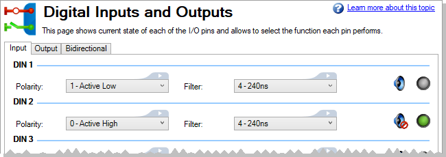
Digital Inputs
Digital inputs can be used as a source for a number of drive functions (Action Table, limit switches, homing, etc). The input becomes active depending on the polarity setting and the wiring setup. Default behavior is the input becomes active (DIN#.STATE = 1) when 24V is applied to the I/O pin (active high). If polarity is set to active low, the input state becomes active when voltage is removed on the I/O pin and becomes low when 24V is applied. An additional signal filter can be configured on each I/O pin to filter out glitches.
| Element | Description | Parameter |
|---|---|---|
| Polarity |
Set when the input state becomes active, when the polarity is High or Low.
|
DIN#.INV |
| Filter |
Setting a filter blocks input changes from registering until the specified pulse width is exceeded.
|
DIN#.FILTER |
| Alert | An alert sound can be played through the PC when the state changes. | |
| LED icon | This LED displays the state of the input, green for Active, off for Inactive. | DIN#.STATE |
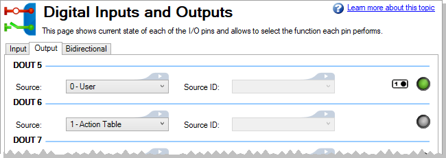
Digital Outputs
Digital outputs can be driven manually with DOUT#.STATEU or as an indication driven by another module. The behavior of each digital output is controlled based on DOUT#.SOURCE. When activated, the digital output will provide 24V on the IO pin.
| Element | Description | Parameter |
|---|---|---|
| Source |
Set the source of the digital output.
|
DOUT#.SOURCE |
| Source ID | Sets the source ID of the selected source when required. In some cases, the source could have several instances and the user has to select which one to use. | DOUT#.SOURCEID |
| On/Off Switch | This item is available when the Source is set to 0 - User. This applies voltage to  or removes voltage from or removes voltage from  the I/O pin. the I/O pin. |
DOUT#.STATEU |
| LED icon | This LED displays the state of the output, green for Active, off for Inactive. | DOUT#.STATE |
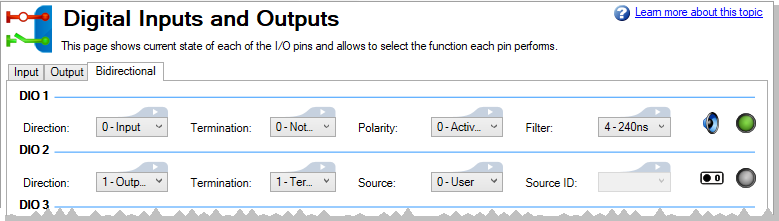
Bi-Directional I/O
The drive has a number of bi-directional I/O on the X22 and X23 connectors. DIO1-2 are on X22 and DIO3-6 are on X23. These can be used as general purpose I/O when the corresponding X22/X23.MODE keywords are set to GPIO (default). DIO#.DIR controls which direction that I/O will operate in. When configured as an input, the associated input keywords are available and the signal can be used for any input function. Likewise, when configured in the output direction, the associated output keywords are available and the signal can be used for any output function.
-
- X22/X23 connectors and corresponding bi-directional I/O may not be available depending on the drive model being used.
| Element | Descripion | Parameter |
|---|---|---|
| Direction |
Set whether the I/O is used as an input or output.
|
DIO#.DIR |
| Termination |
Set whether the I/O is terminated or not.
|
DIO#.TERM |
| Polarity |
Set the polarity of the I/O when it is configured as an input,
|
DIO#.INV |
| Filter |
This item is available when the I/O is configured as an input. Setting a filter blocks input changes from registering until the specified pulse width is exceeded.
|
DIO#.FILTER |
| Source |
Set the source of the I/O when it is configured as an output.
|
DIO#.SOURCE |
| Source ID | Sets the source ID of the selected source when required. In some cases, the source could have several instances and the user has to select which one to use. | DIO#.SOURCEID |
Related Topics
Actions Table | Hardware Enable | Hardware Limit Switches | Capture


